Tags: engineering reverse
Rating: 5.0
## Analysis
The supplied binary is an x86_64 ELF.
`main` allocates a very large buffer and passes it on to some inner functions, but there is a conspicuous lack of user input.
The function at `0x1420` looks interesting, it gets this giant buffer as an input and consists of a very large `switch` statement:
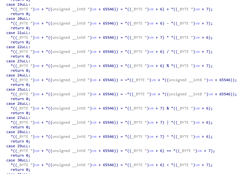
### It's a VM!
Based on the body of each option, it looks a lot like a virtual machine, with each branch of the `switch` implementing a single instruction and operating on the giant buffer (our VM state). Let's call this function `vm_advance`.
By looking at how the big bad buffer is used, both in the constructor at `0x13B0` and in `vm_advance`, we can make some assumptions about its format:
```
struct VM
{
uint8_t reg[8];
uint8_t memory[65536];
uint8_t PC_H;
uint8_t PC_L;
uint8_t rI;
uint8_t rX;
uint32_t rM;
uint8_t write_buffer[256];
uint8_t some_value;
};
```
It has some general purpose registers, some special purpose registers, some memory, some kind of a separate write buffer.
Setting up that structure in IDA and providing type information makes `vm_advance` look a bit nicer:
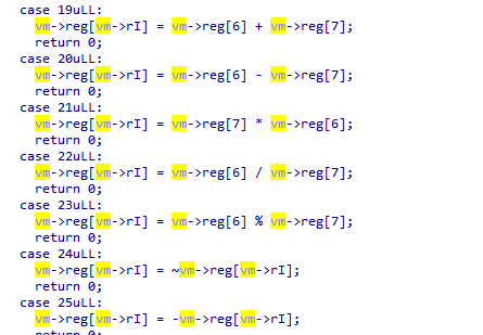
It appears there is a register file of 8 GP registers (8 bits each), an 8-bit index register `RI` which is used to address the register file, a 16-bit program counter `PC`, an unknown register `M` which seems related to branches, and some unknown status and other data.
Most of the op codes are pretty easy to figure out, here is an enum of the opcodes and some friendlier names:
```
enum OP
{
NOP = 0x0,
MOV_RI_0 = 0x1,
MOV_RI_1 = 0x2,
MOV_RI_2 = 0x3,
MOV_RI_3 = 0x4,
MOV_RI_4 = 0x5,
MOV_RI_5 = 0x6,
MOV_RI_6 = 0x7,
MOV_RI_7 = 0x8,
MOV_RRI_REG0 = 0x9,
MOV_RRI_REG1 = 0xA,
MOV_RRI_REG2 = 0xB,
MOV_RRI_REG3 = 0xC,
MOV_RRI_REG4 = 0xD,
MOV_RRI_REG5 = 0xE,
MOV_RRI_REG6 = 0xF,
MOV_RRI_REG7 = 0x10,
INC_RRI = 0x11,
DEC_RRI = 0x12,
ADD_RRI_R6_R7 = 0x13,
SUB_RRI_R6_R7 = 0x14,
MUL_RRI_R6_R7 = 0x15,
DIV_RRI_R6_R7 = 0x16,
MOD_RRI_R6_R7 = 0x17,
INV_RRI_RRI = 0x18,
NEG_RRI_RRI = 0x19,
AND_RRI_R6_R7 = 0x1A,
OR_RRI_R6_R7 = 0x1B,
XOR_RRI_R6_R7 = 0x1C,
EQ_RRI_R6_R7 = 0x1D,
LT_RRI_R6_R7 = 0x1E,
LINK = 0x1F,
BRANCH = 0x20,
LOAD_RRI_R0_R1 = 0x21,
STORE_RRI_R0_R1 = 0x22,
RETURN = 0x23,
GETCHAR_RRI = 0x24,
PUTCHAR_RRI = 0x25,
SET_MODE_0 = 0x26,
SET_MODE_1 = 0x27,
SET_MODE_2 = 0x28,
SET_MODE_3 = 0x29,
};
```
### The instruction set
The following groups of instructions are supported:
1. Assignment to `RI` (one instruction each for values 0-7)
2. Indexed register-register move, on the form `R[RI] = RX`
3. Unary operations on `R[RI]`: INC, DEC, NEG, INV
4. Binary operations on the form `R[RI] = R6 OP R7`: ADD, SUB, MUL, DIV, MOD, AND, OR, XOR, EQ, LT
5. Memory operations on the form `R[RI] = OP {R0,R1}`: LOAD, STORE
6. Read a single byte from user to `R[RI]`
7. Write a single byte to user from `R[RI]`.
8. LINK: Save PC to `{R0,R1}` and `M`to `R2`.
9. RET: Get back the state stored by `LINK`
10. A single conditional branch instruction 0x20
11. A set of instructions to explicitly set the branch mode register `M` to 0, 1, 2 or 3.
The 16-bit operations (LOAD, STORE, BRANCH) use `R0` as the most-significant byte and `R1` as least significant.
The branch mode register M controls how the upper half of `PC` is updated between instructions.
After investigating the `PUTCHAR` implementation, it becomes clear that the VM state has an output buffer in it. This is filled with every byte we write.
### Instruction 0x20
This appears to be the only branch instruction, and it is conditional on `R[RI] & 1 == 1`
```
Branch mode 0: Decrement bank (jump 256 addresses backward)
If the next instruction is 0x0x28 (SET_MODE_2), terminate
Branch mode 1: Increment PC by one.
If the next instruction is 0x29 (SET_MODE_3), terminate
Branch mode 2: Increment bank (jump 256 addresses forward)
If the next instruction is 0x26 (SET_MODE_0), terminate
Branch mode 3: Decrement PC by one.
If the next instruction is 0x27 (SET_MODE_1), terminate
```
This means the machine terminates if there is a trivial infinite loop...?
It's curious that it only branches +/- 1 and +/- 256 instructions, this appears to be some sort of banking mechanism.
### Our goal
Looking back in `main()` of the binary, the VM is "executed" and if the final state has `:)\n0` at the beginning of the output buffer, we win. The challenge will dump the flag for us, so there appears to be no further sploiting needed.
The question for us, then, is _what does the VM execute_?
### The inner program
We can see that there is a giant global buffer of 4900 bytes at `0x40A0` which is copied into our VM's state.
It's not loaded straight into the VM memory, though. Every 256-byte "bank" of the VM's memory gets a 70-byte chunk of instructions written to its beginning. The remaining 186 bytes remain zero. Perhaps the 70 bytes are code and then each bank gets its own segment of RAM to work with, that would make sense.
We had the bright idea to try to disassemble all the 70-byte banks. Since each instruction is exactly one byte, it makes sense to just print them all to the terminal We opted to make each bank a vertical column, so that the flow of instructions resembles regular assembly code. We found a lot of NULL bytes (NOP instructions), so we hid those. A quick bit of python extracts the binary data from the ELF and shuffles it around like `main` does:
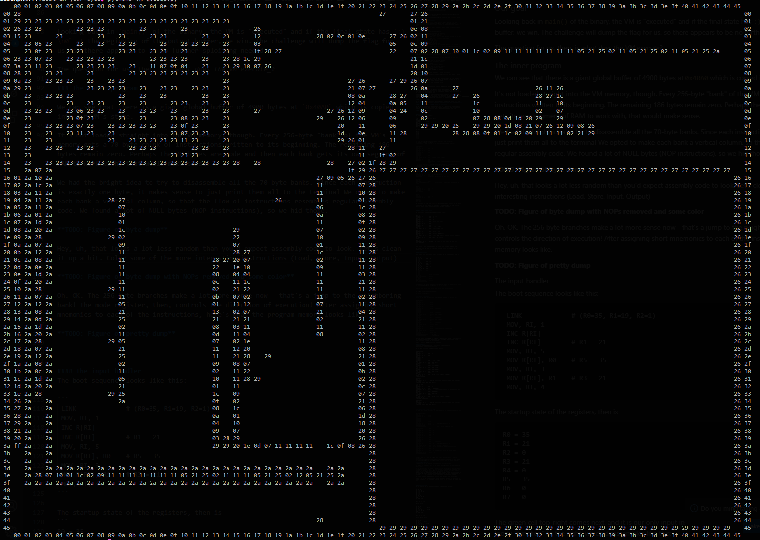
Hey, uh, that looks a lot less random than you'd expect assembly code to look. Let's clean it up a bit. Color some of the more interesting instructions (Load, Store, Input, Output). Assign a short mnemonic to each op code.
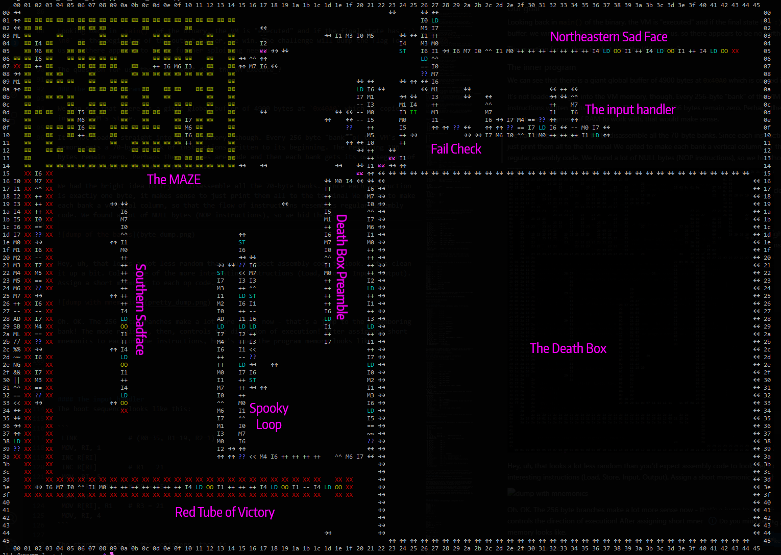
Oh. OK. The 256 byte branches make a lot more sense now - that's a jump to the neighboring bank! The mode register, then, controls the direction of execution! In this program, the PC is a position within this grid, combined with the register which controls its execution direction.
Clearly, there is structure here, and we need to start by reverse-engineering this program. The figure is labeled with the various distinct regions of code. The border shows two-dimensional 16-bit addresses, with the high byte representing a column and the low byte representing a column.
The blue `??` is a BRANCH operation, which will skip the next instruction if the condition holds.
In the following sections, we will use a sort of pseudo-assembly-language to describe all the known instructions. It should be fairly self-explanatory.
### Boot-up
PC starts in the top-right corner at address `0x0000` and execution direction RIGHT.
The boot sequence looks like this (excluding direction change instructions, which will not be mentioned again):
```
LINK # (R0=35, R1=19, R2=1)
MOV, RI, 1
INC R[RI]
INC R[RI] # R1 = 21
MOV, RI, 5
MOV R[RI], R0 # R5 = 35
MOV, RI, 3
MOV R[RI], R1 # R3 = 21
MOV, RI, 4
```
The startup state of the registers, then, is
```
R0=35 R1=21 R2=0 R3=21 R4=0 R5=35 R6=0 R7=0
```
### The input handler
The green instruction near the top-right comes next, and it is our only input instruction.
The read byte is placed in register 4.
It continues to a loopy "function" to the right, which disassembles like this:
```
INPUT_HANDLER:
MOV, RI, 7
MOV R[RI], R6 # R7 = R6
MOV, RI, 0
XOR R[RI], R6, R7 # R0 = 0
MOV, RI, 1
MOV R[RI], R0 # R1 = 0
INC R[RI]
INC R[RI]
INC R[RI] # R1 = 3 (PTR=0x0003)
MOV, RI, 1
LOAD R[RI], [R0.R1] # R1 = *PTR (= 0x15 )
MOV, RI, 7
MOV R[RI], R0 # R7 = 0
DEC R[RI] # R7 = 255
# PTR = 0x0015 (= 0x00 )
# PTR travels down the left-hand edge, iterating through a list of all our op codes
# Each one will be read into R6 until one matches our input. Goody.
CHECK_R4_AGAINST_PTR:
MOV, RI, 6
LOAD R[RI], [R0.R1] # R6 = *(PTR)
MOV, RI, 7
EQ, R[RI], R6, R7 # R6 == 255?
BRA FAILURE
MOV, RI, 7
MOV R[RI], R4 # R7 = R4 (our input byte)
EQ, R[RI], R6, R7 # R7 == R6?
BRA SUCCESS # Input byte must match R6 for us to exit.
LEFT_EDGE:
MOV, RI, 1
INC R[RI] # R1++
GOTO CHECK_R4_AGAINST_PTR # PTR = 0x0015 + (however many laps around we've taken
SUCCESS:
MOV, RI, 6
MOV R[RI], R7 # R6 = R7
XOR R[RI], R6, R7 # R6 = 0
INC R[RI] # R6 = 1
GOTO FAILCHECK
FAILURE:
MOV, RI, 6
MOV R[RI], R7 # R6 = R7
XOR R[RI], R6, R7 # R6 = 0
FAILCHECK:
BRA FINISH
GOTO FAIL
```
The offshoot up and right is a `print(":(")` because the input is incorrect for some reason. Obviously, we can't allow this to execute.
To get out of the input handler, we must submit a byte present in the list between 0x0015 and 0x0039. These values also happen to be valid op codes (notably, not _all_ op codes are present in this allow-list). Interesting.
### What is done to that input?
The vertical exit code after FAILCHECK disassembles like so:
```
MOV, RI, 1
MOV R[RI], R3 # R1 = R3 (=21)
INC R[RI] # R1 = 22
MOV, RI, 3
MOV R[RI], R1 # R3 = 16
MOV, RI, 6
MOV R[RI], R7 # R6 = R7 (our input byte?)
MOV, RI, 0
XOR R[RI], R6, R7 # R0 = 0
MOV, RI, 1
MOV R[RI], R0 # R1 = 0
INC R[RI] # R1 = 1 (PTR = 0x0001)
MOV, RI, 7
LOAD R[RI], [R0.R1] # R7 = *(PTR) (0x29 at boot)
MOV, RI, 0
MOV R[RI], R5 # R0 = R5 (=35 = 0x23)
MOV, RI, 1
MOV R[RI], R3 # R1 = R3 (=16) (PTR=0x2316)
MOV, RI, 6
LOAD R[RI], [R0.R1] # R6 = *(PTR) (0x00 at boot) (top-left corner of death box = 0x00)
EQ, R[RI], R6, R7 # R6 == R7? (No, not yet)
SKIP?
MOV, RI, 4
STORE R[RI], [R0.R1] # *(PTR) = R4 (Store our input byte in the death box!)
GOTO READ_INPUT
```
After storing a value in the death box, the program loops around to read more input.
The program fills the death box with input, column by column, top-to-bottom and then left-to-right. This continues until the entire death box is full.
It certainly looks like our input is a program, since it consists only of a handful of opcodes and is stored inside program memory...
### Death box preamble
After reading input, this snippet of code is executed on the way to the entrance to the box.
```
MOV, RI, 4
MOV R[RI], R0 # R4 = R0
INC R[RI]
INC R[RI]
INC R[RI] # R4 += 3
MOV, RI, 5
MOV R[RI], R1 # R5 = R1
INC R[RI] # R5++
MOV, RI, 6
MOV R[RI], R7 # R6 = R7
MOV, RI, 0
XOR R[RI], R6, R7 # R0 = 0
MOV, RI, 1
MOV R[RI], R0 # R1 = 0
INC R[RI]
INC R[RI]
INC R[RI]
INC R[RI] # R1 = 4 (PTR=0x0004)
MOV, RI, 6
LOAD R[RI], [R0.R1] # R6 = *PTR
MOV, RI, 1
INC R[RI] # R1 = 5
MOV, RI, 7
LOAD R[RI], [R0.R1] # R7 = *PTR
JMP ENTER_THE_DEATH_BOX
```
This appears to set up some parameters for our program, reading the memory locations 0x0004 and 0x0005 and placing them in registers `R6` and `R7` for us.
The first time this code is reached, here's what's in the registers:
```
PC=21,16 R0=00 R1=05 R2=01 R3=16 R4=23 R5=16 R6=00 R7=00 PTR=0x0005
```
The trail leads to the bottom-left corner of the death box and enters it. Our program inside the death box executes.
The exit is at the top-left. Hitting any other wall will just bounce (probably leading to an infinite loop).
### The exit from the box
Exiting the box (rightward at its top-right corner) leads to the straight linear piece of code down its left-hand side:
```
BOX_POSTSCRIPT
MOV, RI, 6
MOV R[RI], R7 # R6 = R7
MOV, RI, 0
XOR R[RI], R6, R7 # R0 = 0
MOV, RI, 7
MOV R[RI], R6 # R7 = R6
MOV, RI, 1
MOV R[RI], R0 # R1 = R0 (PTR=0x0000)
INC R[RI]
INC R[RI]
INC R[RI]
INC R[RI] # R1 = 4 (PTR=0x0004)
MOV, RI, 2
LOAD R[RI], [R0.R1] # R2 = *PTR (0x00 at boot)
INC R[RI] # R2++
MOV, RI, 1
INC R[RI] # R1++ (PTR=0x0005)
MOV, RI, 3
LOAD R[RI], [R0.R1] # R3 = *PTR (0x00 at boot)
INC R[RI] # R3++
MOV, RI, 1
INC R[RI] # R1++ (PTR=0x0006)
MOV, RI, 7
LOAD R[RI], [R0.R1] # R7 = *PTR (0x23)
MOV, RI, 0
MOV R[RI], R2 # R0 = R2
MOV, RI, 1
MOV R[RI], R3 # R1 = R3 (PTR={ (*0x0004)+1 . (*0x0005)+1 })
MOV, RI, 6
LOAD R[RI], [R0.R1] # R6 = *PTR
MOV, RI, 5
EQ, R[RI], R6, R7 # R5 = R6 == R7
INV R[RI]
BRA LOOP_LOWER_ENTRANCE # See below
JMP LOOP_RIGHT_SIDE # Also see below
```
This code appears to use 0x0004 and 0x0005 as a 16-bit pointer. It adds 1 to each dimension
and dereferences the pointer. If the loaded value is not 0x23, the lower path is used.
0x23, conversely, will take the easier top path.
0x23 is a "wall" (a RETURN instruction) in the maze.
### The spooky loop
To the left of the death box lies a swooping loop with two entrances.
That's where we go after the box postscript. This appears to be our only access to STORE instructions, since our program can't contain them.
The top NOPpy entrance at 0x1539 disassembles this way:
```
LOOP_RIGHT_SIDE
MOV, RI, 6
MOV R[RI], R7 # R6 = R7
MOV, RI, 0
XOR R[RI], R6, R7 # R0 = 0
MOV, RI, 1
MOV R[RI], R0
INC R[RI]
INC R[RI]
INC R[RI] # R1 = 3 (ptr = 0x0003)
MOV, RI, 7
LOAD R[RI], [R0.R1] # R7 = *PTR (0x15)
DEC R[RI] # R7 = 0x14
MOV, RI, 1
INC R[RI] # R1++ (ptr = 0x0004)
MOV, RI, 2
LOAD R[RI], [R0.R1] # R2 = *PTR (0x00)
MOV, RI, 1
INC R[RI] # R1++ (PTR = 0x0005)
MOV, RI, 6
LOAD R[RI], [R0.R1] # R6 = *PTR (0x00)
INC R[RI] # R6++
MOV, RI, 3
LT, R[RI], R6, R7 # R3 = R6 < R7 (Loops 0x0005 up to 0x0003)
BRA UP_AND_OUT
JMP RIGHT_AND_DOWN
UP_AND_OUT:
MOV, RI, 6
STORE R[RI], [R0.R1] # *PTR = R6 (Total number of times we've been here, written back to 0x0005)
JMP AROUND_BACK_TO_INPUT_DONE (0x2015)
RIGHT_AND_DOWN:
MOV, RI, 6
MOV R[RI], R7 # R6 = R7
MOV, RI, 3
XOR R[RI], R6, R7 # R3 = 0 (PTR=0x0005)
STORE R[RI], [R0.R1] # *PTR = 0 (clear out the counter of how many times we've been)
MOV, RI, 1
DEC R[RI] # R1-- (PTR=0x0004)
MOV, RI, 6
LOAD R[RI], [R0.R1] # R6 = *PTR (0x00)
INC R[RI] # R6++
MOV, RI, 3
LT, R[RI], R6, R7 # R3 = R6 < R7 (Loops 0x0004 up to 0x0003)
BRA DOWN_AND_OUT
JMP TOWARD_MAZE_ENTRANCE
DOWN_AND_OUT:
MOV, RI, 6
STORE R[RI], [R0.R1] # *PTR = R6 (Total number of times we've been here, written back to 0x0004)
JMP AROUND_BACK_TO_INPUT_DONE (0x2015)
```
### The other side of that spooky loop
The lower (more active) entrance to the same loopy bit in the middle disassembles like this:
```
LOOP_LOWER_ENTRANCE:
MOV, RI, 7
MOV R[RI], R6 # R7 = R6
XOR R[RI], R6, R7 # R7 = 0
NOP
INC R[RI]
INC R[RI]
INC R[RI]
INC R[RI] # R7 = 4
MOV, RI, 6
MOV R[RI], R4 # R6 = R4 # Our program controls R4.
LT, R[RI], R6, R7 # R6 = R6 < R7
BRA LOOP_LEFT_SIDE
JMP LOOP_RIGHT_SIDE # If R is >=4, skip all of this.
LOOP_LEFT_SIDE: # R4 < 4
MOV, RI, 2
MOV R[RI], R0 # R2 = R0
MOV, RI, 3
MOV R[RI], R1 # R3 = R1
MOV, RI, 7
MOV R[RI], R6 # R7 = R6
XOR R[RI], R6, R7 # R7 = 0
MOV, RI, 0
MOV R[RI], R7 # R0 = 0
MOV, RI, 1
MOV R[RI], R0 # R1 = 0
INC R[RI]
INC R[RI] # R1 = 2 (PTR=0x0002)
MOV, RI, 6
MOV R[RI], R4 # R6 = R4 # Our program controls R4
MOV, RI, 7
LOAD R[RI], [R0.R1] # R7 = *PTR # (0x26, a MOVE LEFT)
ADD R[RI], R6, R7 # R7 = R6 + R7 # Convert R4 to a direction instruction
MOV, RI, 0
MOV R[RI], R2 # R0 = R2
MOV, RI, 1
MOV R[RI], R3 # R1 = R3 (Restore PTR to what it was when we came in)
MOV, RI, 7
STORE R[RI], [R0.R1] # *PTR = R3
JMP LOOP_RIGHT_SIDE
```
This part reads `R4`, which must have been set by our program. It will be converted into a direction instruction
(0 for LEFT, 1 for DOWN, 2 for RIGHT and 3 for UP) and written wherever PTR points to when
the code snippet begins. If anything outside of [0,1,2,3] is in R4, nothing is written.
### Looping our program
It appears that the two values at 0x0004 and 0x0005 fill two functions.
The loop in the middle will cycle the two values, sweeping the maze top-to-bottom and then left-to-right.
The box postscript will use them as a pointer, relative to the top-left corner of the maze. If the pointer lands on a "wall", the right-hand side of the store loop is executed, which will move the pointer and execute again. If the pointer points to not-a-wall, the other side of the store loop is executed first, before moving the pointer.
What this means is: each non-wall part of the maze, in order, is optionally written by our program. We do this by "returning" a different value of `R4` each time the program is executed. 0,1,2,3 for directional arrows, anything else to leave a tile unaffected.
The program must also handle the wall positions, even though no write is carried out.
Luckily, `R6` and `R7` contain our maze pointer before each iteration, so we can write our program accordingly. `R6` is the high byte (the column) and `R7` contains the low byte (the row).
### The final stretch
There is a red tube attached to the exit of the maze. If we reach the end of the red tube, our victorious `:(\n` is printed for us, so this must be our goal.
The tube begins with a gauntlet of checks:
```
MOV, RI, 6
MOV R[RI], R7
XOR R[RI], R6, R7
INC R[RI]
INC R[RI]
INC R[RI]
MOV, RI, 0
EQ, R[RI], R6, R7
SKIP?
SET, DIR, RIGHT
```
(Fail if `R7` != 3)
R6 = 3, R7 = 3
```
MOV, RI, 6
DEC R[RI] # R6 = 2
MOV, RI, 7
MOV R[RI], R5 # R7 = R5
EQ, R[RI], R6, R7
SKIP?
SET, DIR, RIGHT
```
(Fail if `R5` != 2)
R5 = 2, R6 = 2, R7 = 1
```
MOV, RI, 6
DEC R[RI] # R6 = 1
MOV, RI, 7
MOV R[RI], R4 # R7 = R4
EQ, R[RI], R6, R7
SKIP?
SET, DIR, RIGHT
```
(Fail if `R4`!= 1)
R4 = 1, R5 = 2, R6 = 1, R7 = 1
```
MOV, RI, 6
DEC R[RI] # R6 = 0
MOV, RI, 7
MOV R[RI], R3 # R7 = R3
EQ, R[RI], R6, R7
SKIP?
SET, DIR, RIGHT
```
(Fail if `R3` != 0)
At the entrance of the tube, then, we must guarantee
```
R3 = 0
R4 = 1
R5 = 2
R7 = 3
```
Luckily, code snippets are spread through the maze, which set these registers based on an accumulating value in `R6`.
This means we need to pass through the maze in the proper order, with R6=0 at the entrance. Once through each instruction section, in the order [ Northeast, Northwest, Southwest, Southeast] , and then exit the maze.
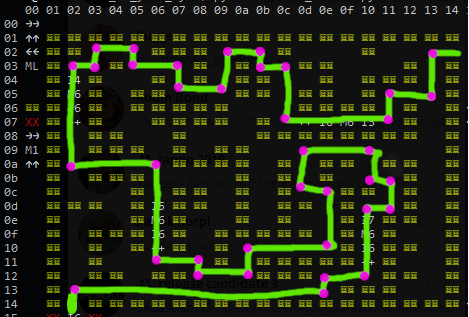
Since we have no control of PC once we enter the maze, we must write directional instructions at well-chosen locations in the maze before we enter. This is what our death box program will do.
The purple spots mark corners where we need to inject direction instructions.
### Implementation
We're ready to solve the maze. What we need is basically a lookup table, such that for certain combinations of `R6, R7` (positions in the maze), we set `R4` to a particular value (direction to write). For any unspecified maze position, set R4 to 5 or something.
A program that behaves this way can be executed as many times as needed.
Based on the solved maze above, our lookup table goes something like this:
(0 for LEFT, 1 for DOWN, 2 for RIGHT and 3 for UP)
```
COL ROW DIRECTION
1 2 Down (1)
1 9 Right (2)
1 18 Down (1)
2 1 Down (1)
2 2 Left (0)
4 1 Left (0)
4 2 Up (3)
5 9 Down (1)
5 16 Right (2)
6 2 Left (0)
6 4 Up (3)
7 16 Down (1)
7 17 Right (2)
8 1 Down (1)
8 4 Left (0)
9 15 Right (2)
9 17 Up (3)
10 1 Left (0)
10 2 Up (3)
11 2 Left (0)
11 6 Up (3)
12 8 Right (2)
12 11 Up (3)
13 11 Left (0)
13 15 Up (3)
13 17 Down (1)
13 18 Left (0)
15 8 Down (1)
15 10 Right (2)
15 12 Down (1)
15 17 Left (0)
16 4 Down (1)
16 6 Left (0)
16 10 Down (1)
16 12 Left (0)
18 1 Down (1)
18 4 Left (0)
```
If we want to be checking for stuff, we need to get the precious values out of `R6` and `R7`. We won't be performing memory ops, so we can use `R0`-`R3` and `R5` freely. Let's use R6 for running comparisons and stash `R7` in a safe place.
To help in this process, we implement a simple assembler which reads a program string formatted as in the dump above (with the short 2-character mnemonics) and generates the byte stream to pass as input to the challenge. See the end of the writeup to download these tools.
Our approach to writing this program is to check one interesting column at a time. If we find that `R6` was 4, we only need to check the rows of interest for column 4.
We devote the two first columns of the death box to preamble code, to set up useful registers etc.
The right-hand and top edge of the death box are sleds of direction instructions, all leading to the exit point. This allows us to `return` from our program by heading for a wall.
We implement each of the column checks as a vertical tower of instructions. If a column is not matched, execution moves on to the next tower.
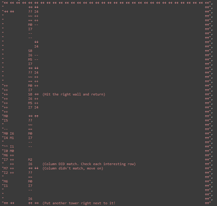
This program checks if `P6=1`, i.e. we're editing column 1 of the maze. If this is the case, execution climbs the tower, checking the row index. If we're controlling an interesting row (2, 9 or 18), we set `R4` apropriately before return. at the top of the tower, if there has been no row match, execution hits the ceiling and exits the box.
By setting up an array of such towers next to each other, we can match all the interesting columns. These towers do fit within the width of the death box!
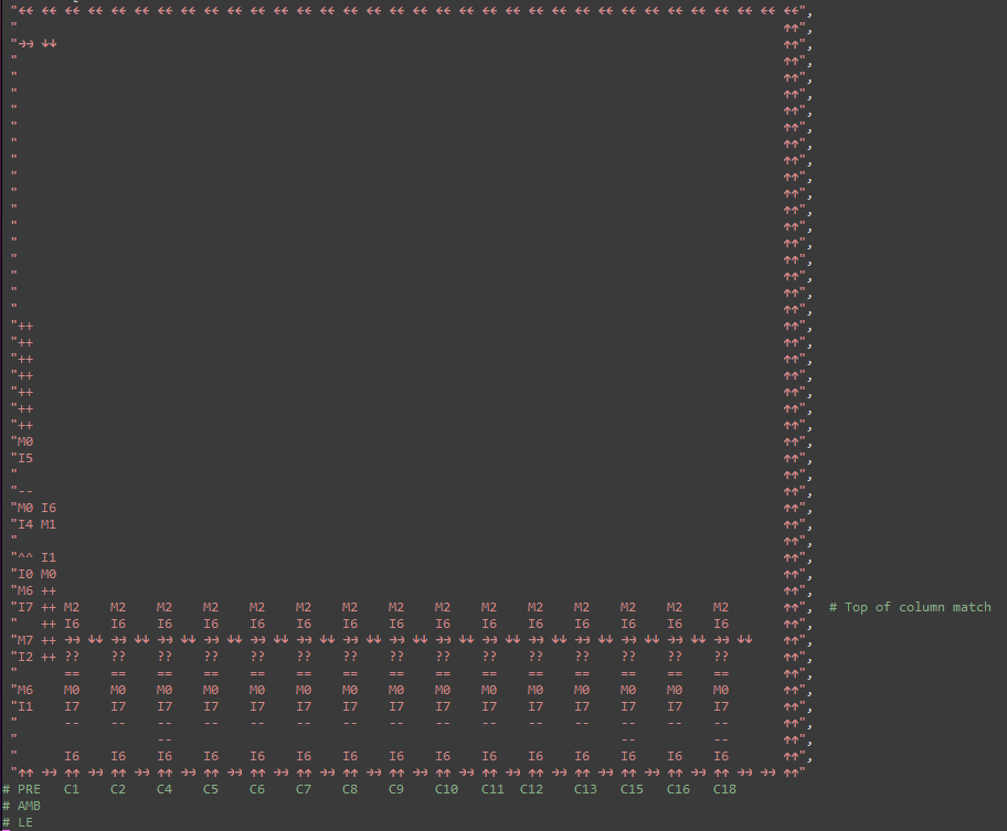
This strategy worked suprisingly well. We packed the output section (generating the proper `R4` on any match) so that some of the towers shared space between them. This allowed the tricker towers (columns 12, 13, 15, 16 each have 4 rows to match!) to use more space. We ended up folding those towers over the top, because they became too tall!
### Testing and running
Obviously, we're not skilled enough to write spaghetti like this and have it execute perfectly on the first try. We need some way to test and iterate, building the program as we go.
Luckily, GDB can be extended with python scripts! That means our dumping code can be integrated into the debugger to show the state of the VM as it executes! EXCELLENT.
By setting a breakpoint at the very beginning of the VM's innermost function (the one that executes a single instruction), we have access to the VM's object (pointer in `$rdi`) and the PC of the VM (calculated into `$rax`).
It is surprisingly uncomplicated to implement custom GDB commands in python:
```python
# This is .gdbinit
source dicevm.py
set pagination off
python
# A command to dump and render the state of the simulation prettily
class VMRender (gdb.Command):
"""
Render the VM's playground
"""
def __init__(self):
super(VMRender, self).__init__("dicevm", gdb.COMMAND_USER)
def invoke(self, arg, from_tty):
# Find the VM's data by snooping on the host's registers
ptr = gdb.parse_and_eval("$rdi")
# Get a python bytes() object with the live data
dump = gdb.inferiors()[0].read_memory(ptr, 0x10114)
dump = dump.tobytes()
# Implemented in dicevm.py
# Print a cool colored rendering of the VM's state
render_full_state(dump)
# Register the command with GDB
VMRender()
# This breakpoint powers our execution. Don't remove it
# pointer to vm struct is in $rdi
# VM's PC is in $rax
VMEXECBP = gdb.Breakpoint("*(0x0000555555554000 + 0x143E)")
# We can control when, in the VM's execution, to break like this:
# End of input validation (column 0x27, row 0x0E)
VMEXECBP.condition = "$rax == 0x270E"
```
This lets us set a GDB breakpoint with a condition on the VM `PC`, so that we can execute in the background until a certain point of interest and then print the VM state. Sweet! We can also remove the condition, letting us "step" through each instruction the VM executes, showing us a step-by-step visualization of the program.
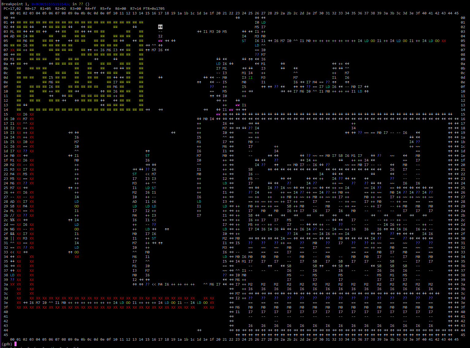
Here's our program in action, right before it enters the maze. As you can see, it has written direction instructions inside the maze to lead the proper way through.
## Flag found! dice{2d_vms_ar3_tw1c3_the_d_of_1d_vms}
This was an _excellent_ RE challenge. Huge thanks to _aplet123_ and the rest of the DiceCTF organizers for such a cool, interesting and rewarding task!
We created quite a bit of custom tooling for this challenge, which you can download [here](https://luftenshjaltar.info/writeups/dicectf2021/rev/lost_in_your_eyes/lost_in_your_eyes.tar.gz) if you're interested.


